
Introduction
When a developer joins the team on an established project, they frequently need to familiarize themselves with the business domain, the system landscape, architecture, component interactions, and more. They need the big picture to understand enough about the system to be productive.
Without this high-level information at their fingertips, they tend to dive head first into the code to try to figure out and piece together some context. Understanding the system this way can be slow and painful.
In this post we’ll look at some ways of concisely diagramming and documenting software architecture and decisions, with artefacts that live alongside our code. Diagrams that are built using open source tools, delivered through almost any medium, and allow us to zoom in or out to our audience’s level of interest.
We’re spoilt for choice when it comes to diagramming tools and strategies, and there is no right or wrong way, but if you’re unsure where to start, I’ll provide some guidance to get the basics in place. This will make life a little easier for the next person joining your team; and as an added bonus, you can use these diagrams to communicate to business stakeholders at any level too.
Context diagram
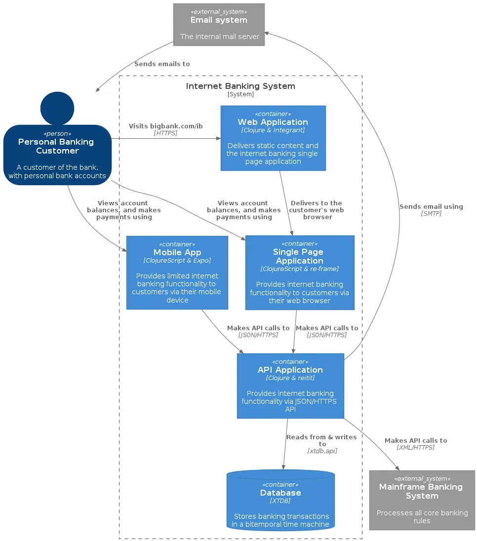
The Context diagram shows the big picture - where the software system fits in with other systems in the wider world.
We’ll use a fictional Internet Banking System as an example, and show (at a high level) how the system fits in to the wider system landscape.
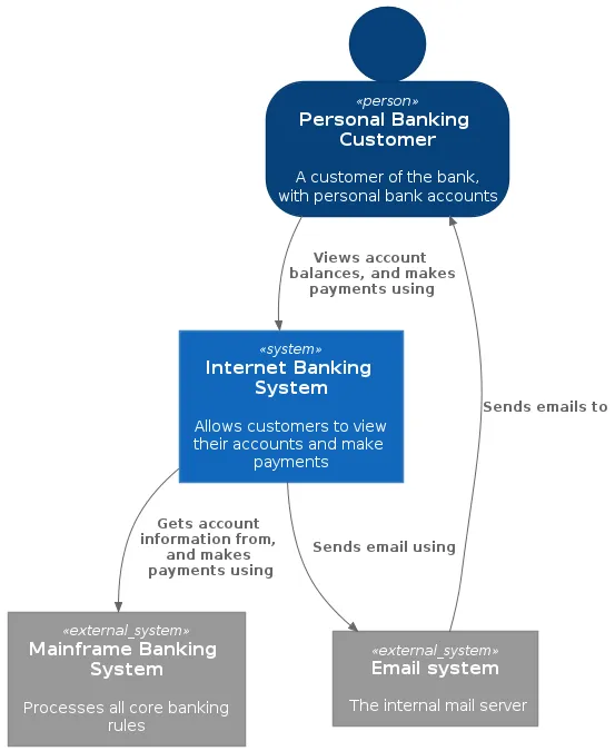
The above diagram was created using PlantUML, a free and open source tool that allows diagrams of all kinds to be expressed in plain text and rendered as images when needed. Using PlantUML’s syntax, the context diagram can be created as follows:
doc/diagram/context.puml
@startuml

!include ./C4/C4_Context.puml

SHOW_PERSON_OUTLINE()

Person(customer, "Personal Banking Customer", "A customer of the bank, with personal bank accounts")

System(system, "Internet Banking System", "Allows customers to view their accounts and make payments")
System_Ext(email, "Email system", "The internal mail server")
System_Ext(mainframe, "Mainframe Banking System", "Processes all core banking rules")

Rel(customer, system, "Views account balances, and makes payments using")
Rel(system, email, "Sends email using")
Rel(email, customer, "Sends emails to")
Rel(system, mainframe, "Gets account information from, and makes payments using")

@enduml
Jump to C4-PlantUML for more detail
Container diagram
The Container diagram shows the major parts making up the software system.
Now let’s zoom in to the system boundary of the Internet Banking System, showing the web server, mobile app, database, etc. A container (not necessarily docker) is some kind of independently deployable unit / process that executes code or stores data.
In plain text, the container diagram can be created as follows:
doc/diagram/container.puml
@startuml

!include ./C4/C4_Container.puml

SHOW_PERSON_OUTLINE()

Person(customer, "Personal Banking Customer", "A customer of the bank, with personal bank accounts")

System_Boundary(boundary, "Internet Banking System") {

        Container(webapp, "Web Application", "Clojure & Integrant", "Delivers static content and the internet banking single page application")
        Container(spa, "Single Page Application", "ClojureScript & re-frame", "Provides internet banking functionality to customers via their web browser")
        Container(mobile, "Mobile App", "ClojureScript & Expo", "Provides limited internet banking functionality to customers via their mobile device")
        Container(api, "API Application", "Clojure & reitit", "Provides internet banking functionality via JSON/HTTPS API")
        ContainerDb(db, "Database", "XTDB", "Stores banking transactions in a bitemporal time machine")

}

System_Ext(email, "Email system", "The internal mail server")
System_Ext(mainframe, "Mainframe Banking System", "Processes all core banking rules")

Rel(customer, webapp, "Visits bigbank.com/ib", HTTPS)
Rel(customer, spa, "Views account balances, and makes payments using")
Rel(customer, mobile, "Views account balances, and makes payments using")
Rel(email, customer, "Sends emails to")
Rel(webapp, spa, "Delivers to the customer's web browser")
Rel(spa, api, "Makes API calls to", "JSON/HTTPS")
Rel(mobile, api, "Makes API calls to", "JSON/HTTPS")
Rel(api, db, "Reads from & writes to", "xtdb.api")
Rel(api, email, "Sends email using", "SMTP")
Rel(api, mainframe, "Makes API calls to", "XML/HTTPS")

@enduml
Jump to C4-PlantUML for more detail
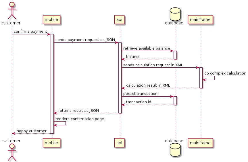
Sequence diagram
The Sequence diagram details the interactions between components of our system and other systems, as well as the order in which they occur.
Sequence diagrams are scenario based; meaning we can create multiple sequence diagrams involving the same set of components. Each sequence diagram represents a different scenario or use case.
Now let’s zoom in further, to a specific scenario: how a payment request from the mobile app gets processed, which systems it calls out to, and when.
In plain text, the sequence diagram can be created as follows:
doc/diagram/sequence/mobile-payment-request.puml
@startuml

actor customer
participant mobile
participant api
database database as db
participant mainframe as main

customer -> mobile ++ : confirms payment

mobile -> api ++ : sends payment request as JSON

api -> db ++ : retrieve available balance
return balance

api -> main ++ : sends calculation request in XML

main -> main : do complex calculation
return calculation result in XML

api -> db ++ : persist transaction
return transaction id

return returns result as JSON

mobile -> mobile : renders confirmation page

return happy customer

@enduml
Decision records
Decision records are used to store the history of how and why the system architecture has evolved over time.
Recording architectural decisions and the motivation behind them can be invaluable for someone new to a project, as these records help them gain a deeper understanding of why things have been done a certain way. Some knowledge of the past can make new decisions easier.
Architecture Decision Records (ADRs) are short text files that document the significant architectural decisions over time.
The basic parts of an ADR are:
-
Title
-
Date
-
Status (proposed, accepted, deprecated, superseded)
-
Context
-
Decision
-
Consequences
In its simplest form each decision record (file) can be manually created and committed to version control, however in these examples we’ve used some basic command line tooling to help maintain the status and numbering of the files.
Initially, we record our decision to use PostgreSQL as the database for our Internet Banking System:
$ adr new Use PostgreSQL to store financial transactionsthis creates a markdown file that we can edit to record our decision:
doc/decision/0002-use-postgresql-to-store-financial-transactions.md
# 2. Use PostgreSQL to store financial transactions

Date: 2021-10-17

## Status

Accepted

## Context

A relational database is required to store financial transactions.

## Decision

We will use PostgreSQL.

## Consequences

PostgreSQL has wide industry adoption.

It is an acceptable tradeoff that horizontal scalability would not be easily achievable.
Later, we realize PostgreSQL might not be sufficient for our needs anymore, and we record a new decision:
$ adr new -s 2 Use XTDB to store financial transactionsthis creates a new markdown file that clearly indicates this decision supersedes a previous one:
doc/decision/0003-use-xtdb-to-store-financial-transactions.md
# 3. Use XTDB to store financial transactions

Date: 2021-11-12

## Status

Accepted

Supersedes [2. Use PostgreSQL to store financial transactions](0002-use-postgresql-to-store-financial-transactions.md)

## Context

The Internet Banking System requires an immutable record of transactions and horizontal scalability.

## Decision

We will use XTDB.

## Consequences

Developers & users will be able to more efficiently query through business time.
our previous decision has been updated automatically, to indicate that it has been superseded:
doc/decision/0002-use-postgresql-to-store-financial-transactions.md
...

## Status

Superseded by [3. Use XTDB to store financial transactions](0003-use-xtdb-to-store-financial-transactions.md)

...
Folder structure
In the above examples, we stored each diagram and decision inside a
doc folder at the root of the project, as plain text files that get
committed to version control and evolve with our source code.
As an added bonus, our diagrams and decision records are indexed, and searchable from within our IDE.
my-app/
├── doc/
│   ├── decision/
│   │   ├─ 0001-first-decision.md
│   │   └─ 0002-second-decision.md
│   └── diagram/
│       ├─ context.puml
│       ├─ container.puml
│       └─ sequence/
│          ├─ my-scenario-one.puml
│          └─ my-scenario-two.puml
└── src/
Tooling
PlantUML
PlantUML is an open source project that allows you to create diagrams using a simple and intuitive text-based language. It has extensive support in popular wikis, forums, text editors and IDEs, and can be used via different programming languages and documentation generators (see the list). Images of diagrams can be generated in PNG, SVG or LaTeX format.
You’ll need these things to run PlantUML:
-
Java
-
Graphviz (optional - you don’t need this if you only need sequence diagrams, but is needed for Context & Container diagrams)
You can now generate diagrams like:
$ java -jar plantuml.jar source-of-your-diagram.pumlPlantUML includes a graphical user interface, if you quickly want to
view an existing .puml file:
$ java -jar plantuml.jar -guihowever, you’ll more likely be using your favorite text editor directly, or calling the CLI inside your CI scripts, read on.
C4-PlantUML
Context and Container diagrams are abstractions introduced in the C4 Model. A full explanation of the C4 Model is out of scope for this post, but the site is recommended reading as it provides more tooling & integration options, and also discusses an interesting contrast between the concepts of diagramming and modeling.
C4-PlantUML combines
the benefits of PlantUML with the C4 Model, to provide a simple way of
describing and communicating software architectures. This is achieved by
including the C4_Context.puml or C4_Container.puml in your own
.puml file, making all the necessary C4 element macros & styling
available for use.
The readme
shows how to include a command line argument when generating the
diagrams, so that we can reference these files in our own .puml files
locally without needing internet connectivity. If, for some reason, you
cannot include this argument (maybe your editor or wiki does not make it
easy to alter the PlantUML command) then an alternative approach is
possible:
-
Download the
C4.puml,C4_Context.pumlandC4_Container.pumlinto your project folder atdoc/diagram/C4/ -
Edit & replace the
!includedirectives at the top of bothC4_Context.pumlandC4_Container.pumlwith!include ./C4.pumland!include ./C4_Context.pumlrespectively. -
Include
C4_Context.pumlandC4_Container.pumlin your own.pumlwith either!include ./C4/C4_Context.pumlor!include ./C4/C4_Container.pumlrespectively.
Editor support
Emacs
With plantuml-mode we get
syntax highlighting in our buffer, and preview of our diagram using
C-c C-c
With auto completion, and the exciting prospect of the addition of snippets, we have a very capable diagramming tool available without leaving our editor.
Important note, if you’re concerned with exposing potentially
sensitive information you’ll want to configure the
plantuml-default-exec-mode to render locally instead of remotely (via
the online plantuml server):
(setq plantuml-jar-path "/path/to/your/copy/of/plantuml.jar")
(setq plantuml-default-exec-mode 'jar)
IntelliJ & Visual Studio Code
There are PlantUML plugins available for IntelliJ and Visual Studio Code.
Continuous integration
With our .puml scripts committed to version control, it’s possible to
add some build steps to our CI server to generate & publish our diagrams
automatically:
-
Checkout
.pumlscripts -
Generate images using
java -jar plantuml.jar context.puml -
Copy images to some static file host
-
Include image links in our wiki’s, and even in our project’s readme.
ADR Tools
ADR Tools is a command line tool that helps maintain status and numbering within a collection of decision records.
To install:
-
Download a zip or tar.gz package from adr-tools releases
-
Unzip/untar the package
-
Add the src/ subdirectory to your PATH
-
In the root of your project, initialise the doc/decisions directory with
adr init doc/decision -
For help do
adr help
TL;DR
Here’s the basic steps to get you going:
-
Know the intended audience and elements of a context diagram
-
Know the intended audience and elements of a container diagram
-
Use the elements of context and container diagrams inside your own puml files
-
Scan through the basic syntax of sequence diagrams
-
Generate images from your
.pumlfiles using theplantuml.jarCLI -
Publish where it makes sense, like your project’s readme
-
Record the significant architectural decisions over time using ADRs
-
Now we can all talk the same language!
Source code
The full source code of these examples can be found in the repository communicating-software.
Conclusion
As developers, we’re often working on tight schedules and documentation & diagramming are rarely our top priority. Sometimes the prospect of having to create yet another new diagram from scratch can be daunting, made worse by the myriad of tools, diagram types, and conventions available.
Having the essential high-level diagrams at hand, in a consistent and reproducible manner, should help make the task of talking about our software that little bit easier, less ambiguous, and maybe even fun!